Repair Log 1
A while ago, the game screen went black during play. When I checked the power board, I noticed that the +5V LED was not lit, so it was time to troubleshoot the problem.
There are several test points on the board (shown in the red circles):
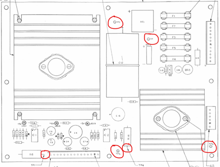
The expected voltages at the test points are:
| Testpoint | Voltage |
|---|---|
| TP1 | +5.1 VDC |
| TP2 | +12.8 VDC |
| TP3 | -14.8 VDC |
| TP4 | +12.8 VDC |
| TP5 | -4.9 VDC |
| TP6 | Ground |
When I measured the board, TP1 was at 3.3V and TP2 showed 3.5V, both far too low.
Transformer Measurements
To check whether the transformer was faulty, I measured the AC voltages:
| Pins | Expected | Actual |
|---|---|---|
| 1,2 → 3,4 | 21.4 VAC | 20.9 VAC |
| 1,2 → 5,6 | 9.7 VAC | 10.4 VAC |
| 3,4 → 5,6 | 9.7 VAC | 10.4 VAC |
| 8 → 9 | 20.9 VAC | 23.9 VAC |
| 11 → 12 | 9.1 VAC | 8.8 VAC |
The readings were a little off, but roughly the same as when I first bought the machine.
Faulty Bridge Rectifier (BR1)
The schematics show that TP2 should have +12.8V and is the first point after the bridge rectifier BR1:
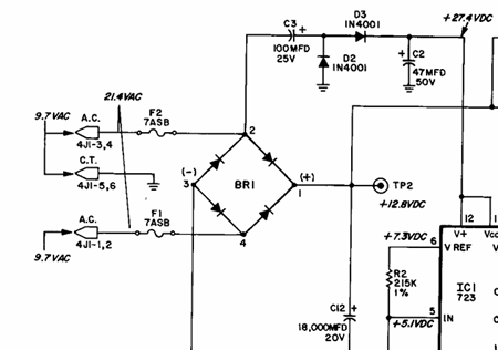 I desoldered the bridge rectifier and tested it—it was faulty.
I replaced it with a new one, and that immediately restored proper operation.
I desoldered the bridge rectifier and tested it—it was faulty.
I replaced it with a new one, and that immediately restored proper operation.
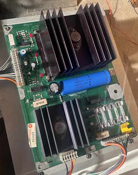
Recapping and Connector Replacement
Since the power board had previously been recapped using radial capacitors where axial ones should have been, and because that always bothered me, I took the opportunity to:
recap the entire power board with the correct form factor, and replace connector 4J1, which connects the transformer to the board.
Everything is now restored and looks much cleaner.