The first step is to make sure that the power is not causing any damage to the boards. After cleaning the power board I disconnected all cables and started testing.
The first thing to test is to see if the transformer is giving the proper voltages.
According to the manual and repair handbook the voltages should be:
| Pin | Should be | As is |
|---|---|---|
| 1,2 => 3,4 | 21,4 VDC | 20,9 VDC |
| 1,2 => 5,6 | 9,7 VDC | 10,4 VDC |
| 3,4 => 5,6 | 9,7 VDC | 10,4 VDC |
| 8 => 9 | 20,9 VDC | 23,9 VDC |
| 11 => 12 | 9,1 VDC | 8,8 VDC |
The voltages are not perfect but I think they might be close enough.
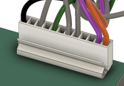
The pin layout is 1 from the left (black wire) and 12 to the right (red wire). The coloring of the wires in the 3d image is not according to the original colors.
Since we have voltage on all pins and they are pretty close to what the nominal values are I dare to connect the cable from the transformer to the power board and start testing. I started testing with the original board that came with the game.
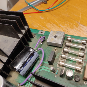
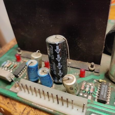
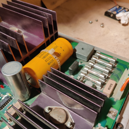
As you can see in these images it is clear that someone has recapped the powerboard. The capacitors are not original and not even the correct ones (the values might be correct though). The correct ones have connectors on the same side, except the big black one that should have a connector in each end of the capacitor.
After a few seconds with the power turned on I heard a small pop and one fuse on the board blew and the 5V LED went black. To me that did not sound very promising so I swapped it to my spare board and tried again. This time no pop and all three LED:s are lit. Feels like I have to order some capacitors for my original board and recap it once again and also check why the fuse blow. That will be another blog post in the future.
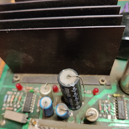
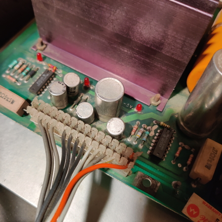
On the power board there are three red LED:s indicating that there is voltage out. There is no guarantee that it is the correct voltages though. It only inicates that it is enough voltage to support a LED.
Here you can see the LED:s, you can also see the replaced capacitors on the original board.
In the images below you can see how a board should look like. This is the spare board that I had laying on the shelf.
Feeling more comfortable I started to measure the board. There are 6 measuring points on the powerboard. I did first a quick measure with no load on the board to see if there was anything dangerous. All voltages looked fine and then I connected the mainboard to the powerboard to get some load. If you measure without a load you might get very strange results.
| Testpoint | Voltage should be | Voltage as is |
|---|---|---|
| TP1 | 5,1 VDC | 4,89 VDC |
| TP2 | 12,8 VDC | 13,8 VDC |
| TP3 | - 14,8 VDC | -14,2 VDC |
| TP4 | + 12 VDC Regulated | 11,86 VDC |
| TP5 | - 4,9 VDC | -5,09 VDC |
| TP6 | Ground | Ground |
So the voltages are good. The +5VDC is the most critical voltage, the RAM chips is very sensitive to high voltages and above 5.15 volt are not healty for them since they tend to burn.
This means that the power line is ok and not it is time to go to the next step. That is to make a testbed for the boards.